Software
Follow Us
|
Tapered keels and rudders can be readily analyzed in
3DFoil and MultiSurface Aerodynamics. In the following article, we will analyze
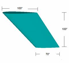
the tapered keel shown below in Figure 1. For this article, we will use the
3DFoil software although the steps are identical for MultiSurface Aerodynamics.
We will use 3DFoil to investigate how two different sweep angles affect the
lift, drag and the location of the center of lateral resistance for a new
keel design.
Keel Planform Setup
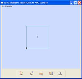
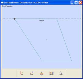
The next step is to change the default surface into the keel of interest. To do this, double-click within the boundary of surface no. 1 on the SurfaceEditor screen to invoke the Edit Surface window show below in Figure 3.
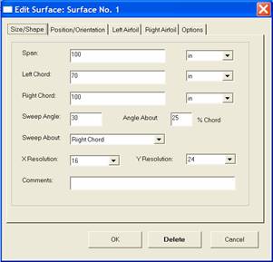
In the edit surface window, change the Span value to 100 and the span unit of dimension from meters (m) to inches (in). We choose to make the right chord the root of the keel and the left chord the tip. In the dialog box, change the Right Chord value to 100 and the unit of dimension from meters (m) to inches (in). Next, change the Left Chord dimension and unit to 70 and inches respectively. For this tutorial, we wish to analyze sweep angles of 30 and 45 degrees. For the first investigation, set the sweep angle to 30 degrees in the Sweep Angle box. The sweep is about the 25% chord line so you must set the About Angle box to 25 % of chord. 3DFoil allows you the option of setting the sweep about the left or right tips of the keel. Here, choose the right tip and click on the right tip option in the Edit Surface dialog box. Figure 4 shows the new setting as they now appear in the Edit Surface dialog box.
Airfoil Settings
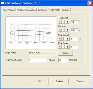
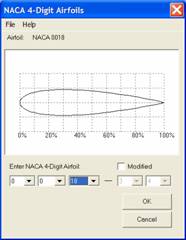
After setting the airfoil for the root, click on the Left Airfoil Tab of the Edit Surface dialog box and repeat the airfoil selection procedure for the airfoil at the tip of the keel. In the NACA 4-Digit Airfoils dialog box (see figure 7), select the NACA 0012 airfoil for the tip instead of the NACA 0018. Figure 8 shows the plan view of the keel as seen in the SurfaceEditor window.
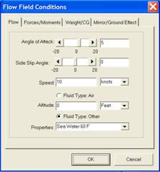
Flow Field Settings To set an angle of attack of 5 degrees, enter 5 in the Angle of Attack box. To set a speed of 10 knots, enter 10 in the Speed box and select units of knots.
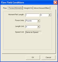
To set water as the fluid, select the Fluid Type: Other button and then select properties of Sea Water 60 Degrees F. The user can select a variety of fluid properties and has the choice of entering a table of water densities, viscosities and vapor pressures. We then click on the Forces/Moments tab to set the results units as shown below in Figure 10. First, set the moment Reference length to 1 meter. The reference length is used in all moment coefficient calculations. Since we wish to display force results in pounds, set the Force Units to Pounds. Set the Length Unit to inches to display the length results in inches. The speed results are displayed in the speed units selected under the Flow tab.
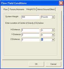
Center of Gravity Settings
Modeling the Hull
Results and Graphs
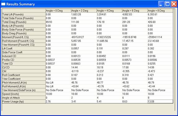
We can use the Reports menu and the Results Summary Table option to create a comparison chart of the keel's performance at a desired set of angles of attack. Figure 15 shows the results for the 30 degrees sweep back angle at the speed of 10 knots. 3DFoil computes lift, drag and moments about the reference location (CG). The program computes the center of lateral resistance for the keel as well. The x-component (horizontal value) is obtained by dividing the pitching moment by the lift. The y-component (depth) is obtained by dividing the roll moment by the lift. The results place the center of lateral resistance a distance of about 49 inches from the keel root leading edge and 44 inches in depth.
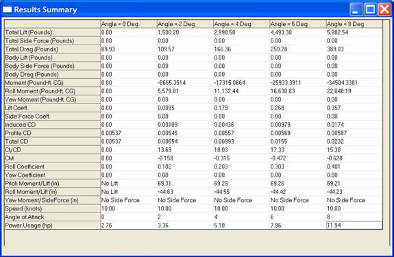
The results for 45 degrees sweep angle places the center of lateral resistance at 69 inches from the root leading edge and 44 inches in depth as shown in Figure 16. For more information about 3DFoil, please visit http://www.hanleyinnovations.com. For availability and price, please call us at (352) 240-3658. More Resources: MultiSurface Aerodynamics |