NASA RAVEN-SWFT eVTOL Aerodynamic Analysis
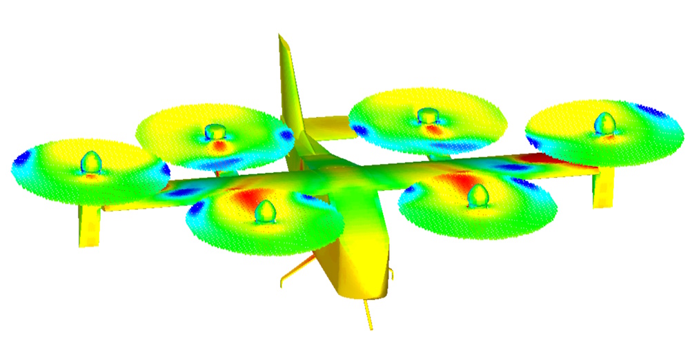
This page presents the results of a Stallion 3D CFD aerodynamics analysis of the NASA RAVEN-SWFT eVTOL in early transition. These preliminary results capture a forward speed of 7 m/s with rotor forces matching 1,000 lbs. Aerospace engineers use Stallion 3D to compute lift, drag, moments and stability derivatives for flight dynamics plant models (FDM) and predict aerodynamic performance.
Key words: Aircraft Aerodynamics, NASA RAVEN-SWFT, eVTOL, CFD analysis
Results Summary
This is a Stallion 3D near-hover simulation of the NASA RAVEN SWFT, a 1,000 lb eVTOL concept, at 7 m/s forward speed. The model includes six lifting rotors with pressure plotted on the aircraft surfaces and actuator disks. The pressure scale shown is approximately 100,950 to 101,450 Pa.
| Aerodynamic Metric | Metric Value | Imperial Value |
|---|---|---|
| Lift (FZ) | -86.31 N | -19.40 lbs |
| Total Drag (FX) | 62.30 N | 14.01 lbs |
| • Pressure Drag | 57.65 N | 12.96 lbs |
| • Friction Drag | 4.65 N | 1.04 lbs |
| Side Force (FY) | -3.08 N | -0.693 lbs |
| Pitching Moment | 175.38 N-m | — |
| Rolling Moment | -1.23 N-m | — |
| Yawing Moment | -9.74 N-m | — |
Ideal Rotor Power Breakdown
The ideal power required across the six actuator disks is distributed as follows, totaling 47,169.70 W:
- Rotor 1: 7,059.38 W
- Rotor 2: 7,065.66 W
- Rotor 3: 6,310.21 W
- Rotor 4: 6,314.22 W
- Rotor 5: 10,189.09 W
- Rotor 6: 10,231.14 W
This is a simple near-hover CFD check, but it shows the type of integrated aircraft, rotor, pressure, force, moment, and power information that can be reviewed directly inside Stallion 3D.
Aerodynamics Analysis Method
The complete workflow scales seamlessly from geometry to final aerodynamic verification inside Stallion 3D:
- Seamless STL Import: Read the NASA RAVEN-SWFT STL geometry created by OpenVSP directly into Stallion 3D, inspect the wireframe, and confirm the correct dimensional units.
- Actuator Disk Configuration: Position each of the six lifting rotors using the precise STL coordinates of the rotor hubs, then define the respective diameters and thrust constraints.
- Automated Grid Generation: Set up the CFD grid. Start with an initial lower resolution for an instant baseline validation check to ensure boundary settings are exact without wasting engineering hours.
- Navier-Stokes Solver: Automatically generate the mesh and execute the flow solver to resolve full surface pressures, force components, and moments. Run higher resolutions as needed to establish mesh independence.
About
Dr. Patrick Hanley is the owner of Hanley Innovations. He received his Ph.D. degree in fluid dynamics from Massachusetts Institute of Technology (MIT) department of Aeronautics and Astronautics (Course XVI). Read more ..
Products
3DFoil
MultiElement Airfoils
MultiSurface Aerodynamics
Stallion 3D
VisualFoil
VisualFoil PLUS
