NASA RAVEN-SWFT eVTOL Aerodynamic Analysis
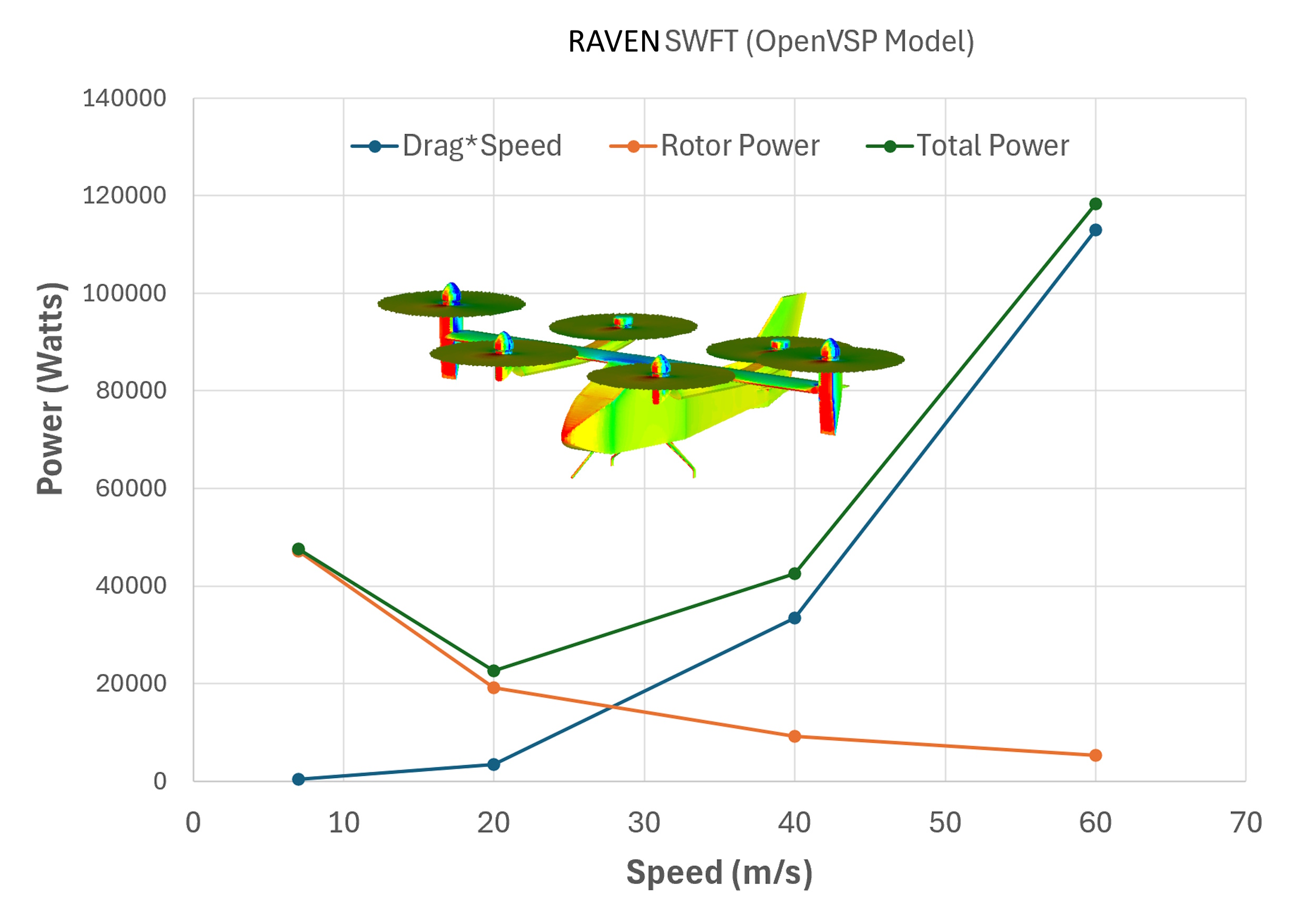
This page presents the results of a Stallion 3D CFD aerodynamics analysis of the NASA RAVEN-SWFT eVTOL for a simple transition analysis. These preliminary results capture forward speeds of 7 m/s to 80 m/s with rotor forces matching 1,000 lbs. Aerospace engineers use Stallion 3D to compute lift, drag, moments and stability derivatives for flight dynamics plant models (FDM) and predict aerodynamic performance.
Key words: Aircraft Aerodynamics, NASA RAVEN-SWFT, eVTOL, CFD analysis
RAVEN-SWFT Transition Speed Sweep
The NASA RAVEN-SWFT configuration can operate initially as a six-rotor hexacopter and then transition toward wing-borne flight. The preliminary Stallion 3D sweep below holds the modeled rotor orientation constant while forward speed increases from 7 to 80 m/s. The results show the transfer of vertical support from the lifting rotors to the aircraft wing and the corresponding change in individual rotor power.
The aircraft weight is approximately 1,000 lb (4,448 N). At 7 m/s the six rotors provide the primary lifting force, while the aircraft surfaces produce a small downward vertical force. At 20 m/s the wing carries only a small fraction of the weight. Near 60 m/s, the calculated wing lift is approximately equal to the aircraft weight. At 80 m/s, the fixed modeled attitude produces lift above the aircraft weight, indicating that a practical flight-control schedule would reduce angle of attack, rotor loading, or both.
| Aerodynamic Metric | 7 m/s | 20 m/s | 40 m/s | 60 m/s | 80 m/s |
|---|---|---|---|---|---|
| Lift Force, FZ (N) | -86.31 | 271.30 | 1,967.53 | 4,566.80 | 8,721.67 |
| Surface Vertical Force / Aircraft Weight | -1.9% | 6.1% | 44.2% | 102.7% | 196.1% |
| Side Force, FY (N) | -3.08 | 3.59 | 13.87 | 29.24 | 57.72 |
| Pressure Drag (N) | 57.65 | 147.99 | 763.83 | 1,730.26 | 2,942.53 |
| Friction Drag (N) | 4.65 | 22.47 | 71.66 | 152.86 | 266.39 |
| Total Drag (N) | 62.30 | 170.46 | 835.49 | 1,883.12 | 3,208.92 |
| Pitch Moment (N-m) | 175.38 | 143.40 | 573.82 | 1,109.32 | 1,813.68 |
| Roll Moment (N-m) | -1.23 | -6.90 | -18.99 | -38.01 | -77.52 |
| Yaw Moment (N-m) | -9.74 | -0.355 | 2.49 | 8.12 | 10.69 |
| Total Rotor Power (W) | 47,169.70 | 19,160.11 | 9,145.47 | 5,299.09 | 3,654.14 |
Individual Rotor Power During Transition
At 7 m/s, all six rotors consume positive power and provide the primary lifting system. The six rotor powers do not change uniformly as speed increases because each rotor experiences a different local inflow and aircraft interaction. As forward speed increases, several rotors enter edgewise flow and eventually produce negative calculated shaft power. In this condition the local aerodynamic loading tends to drive the rotor, indicating autorotation or windmilling rather than normal powered operation.
| Rotor Power | 7 m/s | 20 m/s | 40 m/s | 60 m/s | 80 m/s |
|---|---|---|---|---|---|
| Rotor 1 (W) | 7,059.38 | 2,140.97 | 395.78 | -330.01 | -806.79 |
| Rotor 2 (W) | 7,065.66 | 2,140.15 | 396.93 | -327.10 | -796.02 |
| Rotor 3 (W) | 6,310.21 | 2,262.95 | -207.05 | -1,477.77 | -2,532.68 |
| Rotor 4 (W) | 6,314.22 | 2,261.50 | -207.80 | -1,478.66 | -2,533.81 |
| Rotor 5 (W) | 10,189.09 | 5,174.95 | 4,382.66 | 4,455.64 | 5,160.84 |
| Rotor 6 (W) | 10,231.14 | 5,179.60 | 4,384.96 | 4,457.00 | 5,162.60 |
| Total Rotor Power (W) | 47,169.70 | 19,160.11 | 9,145.47 | 5,299.09 | 3,654.14 |
Rotors 3 and 4 cross into negative power first, followed by Rotors 1 and 2. Rotors 5 and 6 remain powered throughout this speed sweep. This unequal response suggests that the transition controller should manage the rotors in symmetric groups rather than switching all six rotors at one airspeed.
Hexacopter and Tilt-Rotor Transition Strategy
The RAVEN-SWFT can begin the transition as a hexacopter with all six rotor axes approximately vertical. It can then continue the transition as a tilt-rotor aircraft by progressively rotating one or more rotor rows toward the horizontal direction. The flight controller therefore allocates the required aircraft forces among the wing, the forward rotor group, and the aft rotor group.
1. Hexacopter Mode
At 7 m/s and other low forward speeds, all six rotors provide most of the vertical support and control moments. The wing carries only a small percentage of the aircraft weight. Differential rotor thrust provides pitch, roll, and yaw control in the same general manner as a conventional multicopter.
2. Wing-Lift Buildup
As speed increases, dynamic pressure causes wing lift to rise rapidly. The rotor thrust requirement can be reduced while the wing assumes a progressively larger portion of the aircraft weight. Near 60 m/s in the present constant-orientation sweep, the wing produces approximately the full 1,000-lb aircraft weight.
3. Proprotor Tilt
A second family of CFD runs can tilt a rotor row from vertical toward a more horizontal orientation while retaining the same speed stations. Each rotor angle becomes another row in the transition database. Tilting the proprotors redirects part of their force from vertical lift into forward thrust and changes the slipstream interaction with the wing, fuselage, and tail.
| Proprotor Axis Angle | 7 m/s | 20 m/s | 40 m/s | 60 m/s | 80 m/s |
|---|---|---|---|---|---|
| 90 degrees: vertical | Current CFD result | Current CFD result | Current CFD result | Current CFD result | Current CFD result |
| 75 degrees | Planned | Planned | Planned | Planned | Planned |
| 60 degrees | Planned | Planned | Planned | Planned | Planned |
| 45 degrees | Planned | Planned | Planned | Planned | Planned |
| 30 degrees | Planned | Planned | Planned | Planned | Planned |
| 15 degrees | Planned | Planned | Planned | Planned | Planned |
| 0 degrees: horizontal | Planned | Planned | Planned | Planned | Planned |
The completed table can be interpolated to provide a nonlinear transition plant model. Each operating point can include aircraft forces, moments, six individual rotor powers, individual rotor thrusts, wing-lift fraction, and total required power. Independent forward-row and aft-row tilt angles can be added later where greater control-model detail is required.
4. Controlled Rotor Unloading and Shutdown
A rotor should not be switched off based only on airspeed. The controller should verify that the wing has sufficient lift, the rotor thrust command is small, the shaft torque is near zero or negative, and adequate pitch, roll, and yaw control margin remains. An electrically disconnected rotor may continue to accelerate in edgewise flow, so controlled regeneration, braking, feathering, indexing, locking, or folding may be required depending on the final rotor design.
A practical schedule would use hysteresis and time filtering to prevent repeated switching during gusts. Symmetric rotor pairs or rows would normally be unloaded together, unless differential operation is required for trim or a failure case.
Building the Flight-Dynamics Plant Model
Stallion 3D can generate the aerodynamic database required for flight-dynamics and control-system development. The independent variables may include forward speed, aircraft angle of attack, front-row proprotor angle, aft-row proprotor angle, and rotor thrust command. The output table can contain the complete force and moment vector together with individual rotor performance.
- Define operating points: Select forward speeds and proprotor angles covering hover, conversion, and wing-borne flight.
- Run the CFD cases: Use the same aircraft geometry, reference point, rotor numbering, and sign conventions for each case.
- Record the outputs: Export lift, drag, side force, moments, six rotor powers, and six rotor thrusts.
- Locate transition boundaries: Identify wing-weight support, rotor zero-power crossings, excessive moments, and rotor shutdown regions.
- Interpolate the database: Use the resulting lookup tables as the nonlinear aerodynamic plant for a simulator or controller.
This approach changes the CFD study from a collection of isolated flow solutions into a structured transition model. The same database can support normal conversion, rotor-out studies, shutdown scheduling, control allocation, and preliminary verification before flight testing.
About
Dr. Patrick Hanley is the owner of Hanley Innovations. He received his Ph.D. degree in fluid dynamics from Massachusetts Institute of Technology (MIT) department of Aeronautics and Astronautics (Course XVI). Read more ..
Products
3DFoil
MultiElement Airfoils
MultiSurface Aerodynamics
Stallion 3D
VisualFoil
VisualFoil PLUS
