| Products Airfoils Wings Graphing eBooks
Purchase
Contact
|
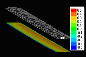
MultiSurface Aerodynamics Hydrofoil Calculations The lifting forces computed by MultiSurface Aerodynamics for a hydrofoil at a finite depth submergence were compared to the experimental data found in NACA Report 1232, "A theoretical and experimental investigation of the lift and drag characteristics of hydrofoils at subcritical and supercritical speeds." by K.L. Waldin et. al. The results were obtained for the subcritical hydrofoils only (MultiElement Airfoils does not consider supercritical hydrofoils). To simulate finite depth, an image hydrofoil was used to model the free surface at the air-water interface. This was implemented in MultiSurface Aerodynamics as a bi-plane (see Fig 1. below). Using the method of images, MultiSurface can be used to analyze general hydrofoil shapes in shallow water. The experiments were carried out for two different hydrofoils; one with an aspect ratio of 10 and the other with an aspect ratio of 4 (presented in Part 2). In all cases, the NACA 64A-412 airfoil was used as the hydrofoil cross section.
The hydrofoil was simulated in MultiSurface Aerodynamics using a grid of 16 X 24. This grid was adequate to obtain a good definition of the airfoil camber line. The NACA 64A-412 airfoil was generated using the NACA 6-digit airfoil generator built into the software. In Part 1, we will look at the comparisons of the lift for the hydrofoil with aspect ratio =10. The depth of submergence of .84 and 3.84 of the chord length were considered. Results for the Aspect Ratio=10 Hydrofoil at a depth of 0.84*Chord. Lift at Speed= 20 fps
Lift at Speed = 30 fps
Results for the Aspect Ratio=10 Hydrofoil at a depth of 3.84*Chord. Lift at Speed= 20 fps
Lift at Speed = 30 fps
Conclusions
Other Results
Back to MultiSurface Aerodynamics.
Copyright © Hanley Innovations 1996-2014 |
